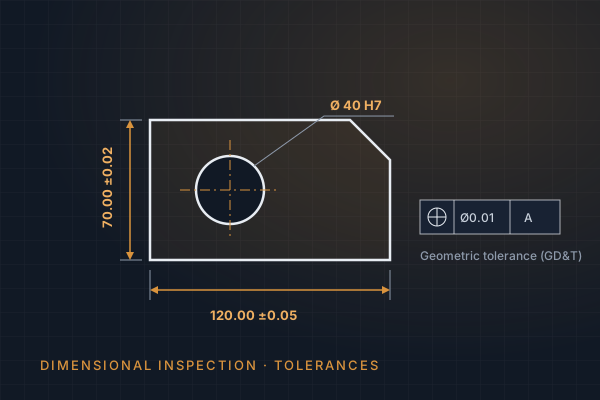
In production, a part must match the dimensions shown on its technical drawing. If it doesn't, it may not fit, may wear quickly or may fail in service. Dimensional inspection is the process of measuring a part and comparing every relevant feature with the drawing — and CIO Inspection carries out visual, geometrical and dimensional inspections with professional measuring equipment.
What is an engineering tolerance?
No manufacturing process can produce a perfect dimension every time. A tolerance defines how much a dimension is allowed to vary while the part still functions correctly. For example, 120.00 ±0.05 mm means any measured value between 119.95 mm and 120.05 mm is acceptable.
Tolerances are a balance: too loose, and parts may not fit or perform; too tight, and manufacturing becomes slow and expensive without any functional benefit.
Types of tolerances
Linear (size) tolerances
Limits applied directly to a length, width, diameter or depth, written as ± values or as upper and lower limits.
General tolerances
Many drawings refer to a general tolerance standard such as ISO 2768 (classes f, m, c, v) for dimensions without an individual tolerance. These must be checked too — they are part of the requirement.
Fits
Shaft and hole tolerances such as Ø40 H7/g6 follow the ISO system of limits and fits (ISO 286) and define clearance, transition or interference fits.
Geometric tolerances (GD&T)
Geometric Dimensioning and Tolerancing controls the form, orientation, location and run-out of features relative to datums — for example flatness, perpendicularity, position, concentricity and profile. GD&T is defined in ISO GPS standards (such as ISO 1101) and ASME Y14.5.
| Category | Examples |
|---|---|
| Form | Straightness, flatness, roundness, cylindricity |
| Orientation | Parallelism, perpendicularity, angularity |
| Location | Position, concentricity, symmetry |
| Run-out | Circular run-out, total run-out |
| Profile | Profile of a line, profile of a surface |
Measuring equipment
The right instrument depends on the feature and the tolerance. A useful rule of thumb is that the measuring instrument should be at least ten times more precise than the tolerance being checked. Typical equipment includes:
- Vernier and digital calipers, micrometers and depth gauges
- Dial and test indicators, height gauges and surface plates
- Bore gauges, thread gauges and plug/ring gauges
- Radius, feeler and angle gauges
- Coordinate measuring machines (CMM) for complex geometry
Calibration and measurement reliability
A measurement is only as good as the instrument and method behind it. Instruments must be calibrated against traceable standards, and the measurement system should be evaluated — for example with a gauge repeatability and reproducibility (Gauge R&R) study — to make sure variation comes from the parts, not the measuring process.
Measurement uncertainty matters most close to the tolerance limits. A part measured at 120.049 mm with an uncertainty of ±0.01 mm cannot be confidently called "in tolerance".
The dimensional inspection report
Every inspection ends with a clear report that includes:
- A ballooned drawing with each characteristic numbered
- Nominal value, tolerance, measured value and pass/fail result
- Equipment used and calibration status
- Photographs and notes on visual defects
- Where defects are found: likely causes and recommendations to eliminate them
To see how inspection fits into the full workflow, read Mechanical Inspection: From Drawing to Final Report.
Written by Abbas Ozden, CIO Inspection Ltd — quality control and inspection, Southend-on-Sea, Essex, United Kingdom.