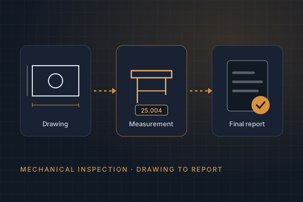
Mechanical inspection verifies that a manufactured part or assembly meets every requirement on its drawing and specification. The measurements themselves are only one part of the job: what makes an inspection reliable is the process around them. Below is the workflow CIO Inspection follows, step by step.
1. Drawing and requirement review
Everything starts with the technical drawing and any related documents — material specifications, surface finish requirements, coatings, standards and customer notes. At this stage we:
- Confirm the correct drawing revision
- Identify critical and key characteristics
- Check general tolerances (for example ISO 2768) and GD&T requirements
- Flag anything ambiguous or difficult to measure before inspection starts
2. Ballooning and the inspection plan
Each dimension, tolerance and note is given a numbered "balloon" on the drawing. The inspection plan then defines, for every balloon, the measurement method, the instrument, the sample size and the acceptance criteria. This makes the inspection repeatable and the results traceable.
3. Preparation
Parts are cleaned and allowed to reach a stable temperature — steel expands roughly 0.012 mm per metre for every degree Celsius, which matters on tight tolerances. Instruments are checked for calibration status and zeroed, and suitable datums and fixturing are prepared.
4. Visual inspection
Before measuring, the part is checked visually for burrs, sharp edges, scratches, dents, porosity, cracks, corrosion, incorrect marking and coating defects. Many costly problems are found at this simple step.
5. Dimensional and geometrical measurement
Each characteristic is measured with the appropriate equipment — calipers, micrometers, height gauges, indicators, bore and thread gauges, or CMM for complex geometry. Geometrical characteristics such as flatness, perpendicularity, position and run-out are measured relative to the datums defined on the drawing. Read more in Dimensional Inspection and Engineering Tolerances.
6. Evaluation and non-conformances
Results are compared with the tolerances. Where a characteristic is out of tolerance, it is recorded as a non-conformance with the measured value, the deviation and photographs. We also highlight characteristics that are within tolerance but close to the limit, as they often indicate a process that is drifting.
7. Root cause and recommendations
Finding a defect is half the job. We look for the likely cause — tool wear, fixturing, machine settings, material, drawing interpretation — and recommend how to eliminate it. For repeat production, SPC can be introduced to monitor critical characteristics.
8. The final inspection report
The report brings everything together in a format you can share with your customer or supplier:
| Section | Contents |
|---|---|
| Header | Part number, drawing revision, quantity, date, inspector |
| Results table | Balloon no., nominal, tolerance, measured value, result |
| Visual findings | Defects found, with photographs |
| Equipment | Instruments used and calibration references |
| Conclusion | Accept / reject / concession, root cause and recommendations |
A clear report protects both sides: the supplier knows exactly what to correct, and the customer has objective evidence for the decision.
Written by Abbas Ozden, CIO Inspection Ltd — quality control and inspection, Southend-on-Sea, Essex, United Kingdom.